Texturing
Material shaders
In older games, a single image qualified as a texture and all that was required was that you simply drop the corresponding image into a specific folder. The general concept in the id Tech 4 family is to use material shaders which in turn use multiple images , each representing a different property of a surface. This makes texturing more work than it was in the past, but it also gives much more power and flexibility to the developers.
Check the following links to learn more about the syntax of material files for Doom 3 . This will help you understand and write them:
Material
declarations
The basic syntax of material shaders is explained here.
Global keywords
Global keywords used in material shaders are indexed in this
article.
Stage keywords
Stage specific material shader keywords are listed in this article.
 Note: Quake 4
only:
Note: Quake 4
only:- You can also use guides to simplify writing many materials that behave the same way.
Diffuse maps
Missing image: /w/images/thumb/6/64/Diffuse_example.jpg/180px-Diffuse_example.jpg An example diffuse map
An example diffuse map (Click to Enlarge)
Diffuse maps in Doom 3 represent the diffuse reflection and color of a surface. In other words they define the color and intensity of light reflected back when it strikes a surface.
The goal when creating a diffuse map is to draw a color map and darken areas where light would be absorbed. For instance, the cracks in a brick wall absorb more light than they reflect back.
The example to the right demonstrates this as the bricks themselves are a greyish value and the cracks between them almost black.
No surface reflects light back at the same intensity it’s recieved. In that respect, it’s a good idea to darken your diffuse maps appropriately. Generally, the smoother a surface is the less light is diffused and the brighter your diffuse map can be.
Diffuse maps are added to material shaders by use of the Diffusemap keyword or the Blend keyword with the “diffusemap” parameter. As convention it’s recommended that you add “_d” to the end of the texture’s filename.
Bump maps
Bump mapping adds an illusion of depth and texture to images. It doesn’t actually alter geometry but rather affects the shading over a surface. There are two different kinds of bump maps useable in the id Tech 4 engine: Normal and height maps.
Normal maps
 An example normal map (Click to
Enlarge)
An example normal map (Click to
Enlarge)
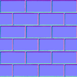
Normal maps define the slope or normals of a surface. In other words, they alter the direction a surface appears to be facing.
The normal for each pixel is defined by storing spacial X,Y,Z transformation data in the R,G,B channels. The example to the right demonstrates this.
There are two methods to create normal maps.
- Render a normal map from 3D geometry
- Convert a height map into a normal map
There are links to tools for use with both methods at the bottom of this page.
 Inverting the
green channel of a normal map.
Inverting the
green channel of a normal map.
Depending on the tool used to render normal maps, you may need to invert the green channel of the resulting image in order for your normal map to render properly in game. When viewing the green channel of the image, it should appear as if it’s being illuminated from the bottom.
Normal bump maps are added to material shaders by use of the Bumpmap keyword or the Blend keyword with the “bumpmap” parameter. As convention it’s recommended that you add “_local” to the end of the texture’s filename.
Height maps
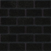
 An example height map
Height maps are greyscale images that define the height of the indivdual pixels of a surface. They adjust the visual depth of a texture.
The height of each pixel is defined by the brightness of the image. A white pixel is as high, a black pixel is as low as it gets. grey levels in between represent different heights.
Heightmaps are usually painted in an image manipulation program. There is usually no need to render those. Note that height maps are converted to normalmaps by the id Tech 4 engine when loaded. The use of height maps is only to allow for an easier workflow.
Height bump maps are added to a material by use of the Heightmap function. As convention it’s recommended that you add “_h” to the end of the texture’s filename. find your style
Normal maps vs. height maps
The id Tech 4 engine is able to combine both a normal map and a height map into one combined bump map.
Usually this is done when it’s more practical to paint fine details into a height map than it is to model the same details and render them into the corresponding normal map.
Normal and height bump maps can be combined in a material by using Addnormals function.
It should be noted however, that height maps by default do not visually displace a surface in id Tech 4 engine based games. They only serve as a means to compute surface normals for use with dynamic lighting.
What this means is that essentially, a height map is converted into a normal map. And because the only way to compute slope when dealing with height is to compare each pixel value to that of it’s neighbors, a height map can never be as detailed as a normal map of the same resolution.
More evidence to back up this claim is that height maps do not make efficient use of multiple color channels as a height map saved in RGB color space is still black and white. Because the data in each color channel is redundant, you are limited to only 256 levels of intensity.
Compare this to normal maps where each channel can be unique and it’s clear that normal maps are more efficient at defining slope.
Specular maps
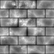
 An example specular map
Specular maps in Doom 3 represent the specular intensity and color of highlights on a surface. In other words they define the “shinyness” and color of specular reflections.
The brighter a specular map is, the more shine is applied to the final material.
The goal when creating a specular map is to fill the image with a solid value to represent the general specularity of the surface and then darken areas where weathering would occur.
The example at right has a mistake; the face of a brick would recieve less wear and tear than the edges and should therefore be more specular. Note that the cracks themselves have little to no specularity at all.
Color applied to a specular map tints the color of highlights. Bricks are made out of a sand like material and as such would reflect slightly variable tints. This too is present in the example to the right.
Specular maps are added to material shaders by use of the Specularmap keyword or the Blend keyword with the “specularmap” parameter. As convention it’s recommended that you add “_s” to the end of the texture’s filename.
Bump maps can be modified into a good starting point for a specular map. See Start a Specular map with a Normal map .
Hit maps
The information in this section is specific to Quake 4 .
Hit maps are special images mainly used for animated models. These are made up of simple patches of color that follow the RGB values given in a materialtype . When an area of the model is hit a different impact effect is played depending on the hit map color of the area hit. Usually smaller resolution hitmaps are used compared to regular skins as detail does not need to be as high as the diffuse or normal map.
Hit maps are added to material shaders by use of the materialImage keyword. As convention it’s recommended that you add “_hit” to the end of the texture’s filename.
Sky and reflective maps
Both sky and reflective materials make use of cube maps (also known as environment maps).
The Doom 3:ROE expansion pack and Quake 4 add sky portal functionality to the engine which does away with the need to use cube maps for sky materials.
Seamless Textures
Missing image: /w/images/thumb/6/64/Diffuse_example.jpg/200px-Diffuse_example.jpg
Missing image: /w/images/thumb/6/64/Diffuse_example.jpg/200px-Diffuse_example.jpg
Most level textures are designed to be placed next to each other without any visual discrepancies. Many ceiling, wall, and floor textures are designed in this manner, so a long area can have this texture applied, without forcing the mapper to stretch and reduce the quality of the texture.
The example on the right shows how textures will tile horizontally when designed properly. Two copies of the above image are placed side-by-side, and the bricks line up.
This texture can also be tiled vertically. The edges of the texture at the top finish each brick, and the edges at the bottom do not finish the brick. When placed on top of each other, the alternating pattern is not disrupted, and no visual break occurs.
This effect can be achieved using the offset tool in either The GIMP or in Adobe Photoshop . Other image manipulation suites may offer other similar tools, please refer to the documentation with your package to find such a feature.
See Creating Seamless Textures for several tutorials on how to use this tool to create seamless textures, as well as links to several plugins that perform the transformation automatically.
Supported image formats
The Doom 3 engine supports the following image formats:
Details on each format and it’s quirks can be found by following the links above.
Dynamic Internal Images
The engine has a set of internal image maps that are used for various special purposes. These images can be reference in material shaders and they can also be applied to surfaces as if they were materials in their own right.
The names and purposes of these images are…
- _black - A pure black image map.
- _cubicLight - ???
- _currentRender - The current rendered image on screen. Used primarily as the input for fragment programs.
- _default - ???
- _flat - A flat normal map.
- _fog - The internal fog image.
- _noFalloff - ??? Used as the light falloff image for lights with no falloff.
- _pointLight1 - ???
- _pointLight2 - ???
- _pointLight3 - ???
- _quadratic - ???
- _scratch - An image buffer. Used primarily when rendering mirrors.
- _spotlight - ???
- _white - A pure white image map.
Compressed and uncompressed
If you look at the vanilla texture assets, you’ll notice that Doom 3 has TGA and DDS versions of each image in the game. The TGA files are used when running in high or ultra quality mode (in high quality, the diffuse maps use the compressed DDS files, but the normal maps use the uncompressed TGA files). In all other modes only DDS files are used.
If no corresponding DDS file exists, Doom 3 generates one for use this session, this run-time compression means that while you can run in a lower quality than ultra , you won’t actually have any DDS files to distribute. It’s recommended therefore that you create your own DDS files as relying on Doom 3’s automatic generation slows down loading significantly.
You can bypass the DDS files and load the TGA files directly by setting image_usePrecompressedTextures to 0. The images will still be compressed dynamically at load time, but since you’ll be forcing the game to use the TGA files the results of changes to the images will be immediately apparent. You can bypass compression by setting image_useCompression and image_useNormalCompression to 0.
The DDS files used in Doom 3 were created with the following settings:
- Normal Maps: “RXGB +red 0.0 +green 0.5 +blue 0.5”;
- Specular: “DXT1”;
- Diffuse (no alpha): “DXT1”;
- Diffuse (w/ alpha): “DXT3”;
You can use the following command line arguments with ATI’s The Compressonator:
thecompressonator -convert "normal.tga" "normal.dds" RXGB +red 0.0 +green 0.5 +blue 0.5 -mipmaps
thecompressonator -convert "specular.tga" "specular.dds" DXT1 -mipmaps
thecompressonator -convert "diffuse.tga" "diffuse.dds" DXT1 -mipmaps
thecompressonator -convert "diffuse.tga" "diffuse.dds" DXT3 -mipmaps
Compression Notes
See the modding page for how to automatically compress all your assets for distribution.
DDS files, and their MIP Maps, can be edited. See Editing MIP Maps .
If one is not using ATI’s The Compressonator, local maps can be prepared for compression manually. Simply copy the red channel to the alpha channel. Then delete the old red channel (to save space). The advantage to interpriting local maps in this manner, we can presume, is due to the alpha channel’s higher quality. In DXT5 each 4x4 (16) pixel block is encoded with 64 bits of RGB color data, and 64 bits of alpha data. Since a local map primarily consists of only 2 channels (horizontal, usually red, and vertical, usually green), we’re effectively splitting the two channels evenly across the compression scheme.
See also
General image editing applications
Seamless texture creation tools
- The Resynthesizer - GIMP Plugin
- Filter Forge - Photoshop Plugin
- Map Zone
- Texture Maker
- Genetica
- DarkTree
- FxGen