How to add a terrain
This step-by-step tutorial will demonstrate how level designers, with no prior modelling experience, can easily create good terrains for 3D skyboxes as well as interactive terrain with a little more work using only free applications. Whereas many more utilities and procedures could be thrown in, an effort has been paid on optimising the art pipeline. Once you are familiar with this method you can easily branch out and seek more specialized knowledge.
Overview
This method has the following overarching structure:
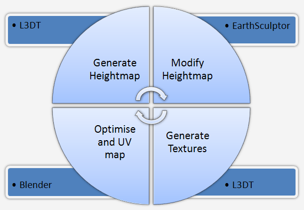
This is an iterative process: you may need a couple of passes to get exactly what you want. Unfortunately, since the id Tech 4 engine doesn’t have a dedicated terrain editor some back-and-forth is inevitable.
Requirements
You’ll need these free utilities to use this tutorial:
- L3DT Standard Edition v2.4 – Primarily a terrain generator. We’ll use it to generate our preliminary heightmap and create textures for the final terrain.
- Earth Sculptor v0.25 BETA – A heightmap-based terrain editor. For this tutorial we’ll use it to shape the terrain generated with L3DT.
- Blender – The free modelling application to convert from heightmap to a 3D model and generate UV mapping coordinates.
- ASE exporter for Blender – To export our terrain model from Blender to ASCII Scene Export format all id Tech 4 games can load. Local mirror (43KB)
Note: The versions mentioned above are the ones used when this article was written. For some of these programs a newer version may be preferable.
Step one: Generate heightmap
This initial stage will produce a heightmap file that we’ll use as a base for later editing. If you already have a heightmap or you want to start completely from scratch you should skip this step.
Start L3DT, go to the File menu and select “New map…” and you should be greeted with the following dialogue box; choose the first option “Design/inflate” and click “Next”. You can try some of the other methods but this one is the fastest and usually wields the best results.
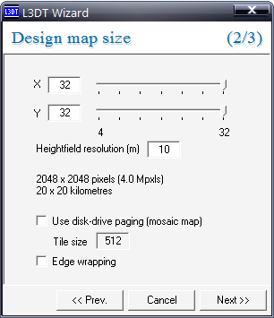
In this next screen you should move the two slider positions all the way to the right until it says “2048 x 2048 (4.0 Mpxls)” below them. For now leave all the other options intact though when you feel more comfortable you could play around with the heightfield resolution factor. The “mosaic map” option is of no use here, however, enabling “edge wrapping” will allow you to tile the terrain seamlessly. This has little value for large scale terrains, which are the purpose of this tutorial, but it may allow you to use this program to generate standard textures like dirt or rock.
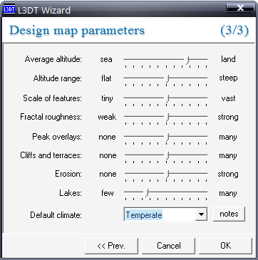
When using the “Design/inflate” method you get this third screen where you can tailor the terrain to your liking by tweaking the parameters defined here. They are all pretty much self-explanatory however you should raise the average altitude on the first slider and lower the frequency of lakes in the last one for best results. The “scale of features” slider is helpful when you want to create a terrain for a 3D skybox (“vast”) or interactive terrain (“tiny”). Finally, the “notes” button at the bottom provides helpful tips on your choice of default climate. Don’t be alarmed if it takes a few tries to get just the terrain you want but don’t agonise about getting it absolutely right since you’ll be able to change the landscape later on; simply make sure you have the major geographic details where you want them and don’t worry about exact steepness of a certain hill. Click “OK” when you’re satisfied.
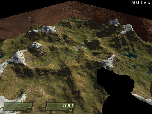
After a few seconds, you should be looking at something similar to the image below. This terrain was generated without tweaking either the average altitude or the lake frequency which, as you can attest, can lead to terrains with plenty of water bias. As we shall see later on, even if you want water in your terrain putting it here instead of the level editor has some drawbacks.
L3DT allows you to modify the generated design by double clicking on each specific “pixel”. You can change altitude, climate or change a specific mount into a volcano just to give an example. You can spend hours literally shaping your terrain however, for the purpose of this tutorial we’ll assume you have finished the terrain generation phase.
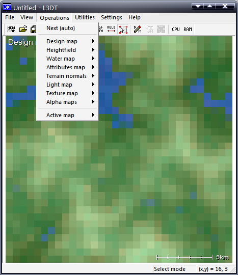
If you click “Operations” in the menu you’ll see all the layers the program uses. Although we only need a couple you usually have to generate them all and in order. That’s what the first option “Next (auto)” does. However, we’re going to go step-by-step here. After the design map which we’ve just finished comes the heightfield which is, in all ways we care about, the same as a heightmap used by the id Tech 4 engine. Click on “Heightfield > generate map” and wait until the application finishes. These are lengthy operations that can, depending on your terrain complexity, take a couple of minutes even on fairly fast CPUs.
Now go to the “File” menu, highlight “Export” and select “Active map…”. In the screen that appears, make sure you select “Bitmap” and that the width and height fields read “2048”; browse to where you want to save the image and click “OK”. For the purpose of this tutorial let’s name it “heightfield.bmp”. Leave the other options alone for now.
Step two: Modify heightmap
Once you have a base heightmap you’ll want to modify it so it works better in-game, especially for interactive terrains. If you’re doing a terrain to put as scenery in a 3D Skybox you probably won’t need to modify it and can skip this section.
Start EarthSculptor and go into “Utility > Import Heightmap” and select the “heightfield.bmp” file we generated previously. The programme should now generate the terrain for you. EarthSculptor is very easy to work with so there’s no need for an extensive walkthrough, you’ll spend most of your time in the “Terraform” tool (select it by clicking on the second button of the toolbar). Although you’ll want to setup water (if any) in the level editor it may be useful to enable water in EarthSculptor even if your terrain doesn’t have any water at all. The water line will give you a good sense of scale. Also, you may need to edit the “terrain height” scale value.
When you’ve finished terraforming your terrain, select “Utility > Export Heightmap”, let’s use “heightmap.png” this time.
Step three: Generate Textures
Start L3DT again but this time go to “File > Import > Heightfield…” and select our “heightmap.png above.
Okay, now we’ll generate the next terrain layer. Go to “Operations” and select “Water map > flood wizard”. You can click “Next” in the screen that first appears while in the second one shown below you may want to change the “Salin > EnableFlag” to false (unless of course it makes sense for your terrain). Click “OK” and wait another couple of minutes. When it’s done, go into “Operations” and select the next layer “Attributes map > Generate map”. Continue to the next one “Terrain normals”. You’ll notice that it has generated what seems like a regular normalmap used by id Tech 4 engine. Go to “File > Export > Active map…”. Again, choose “Bitmap” and browse to where you want to save. We’ll call this one “normalmap.bmp”.
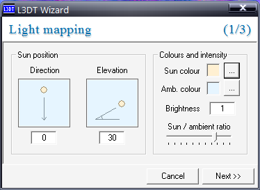
After that, generate the next layer: the “Light map”. You’ll be asked to enter some values but you can leave all of them on default with the exception of the Sun’s position in the first screen shown below, as you’ll want to make sure the parameters here match the lighting on your level.
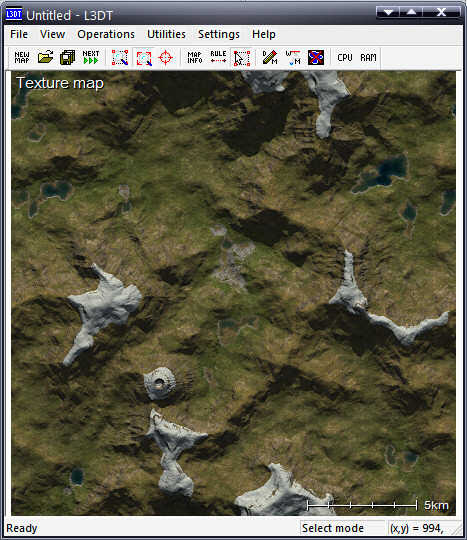
When you’re done, proceed to generate the last layer we need, the “Texture map” in the Operations menu. In the single screen that appears, make sure the first three options are enabled and all the rest are disabled and click “OK”; after a few seconds you should have something similar to this:
Export this layer as a bitmap also; we’ll name it “texturemap.bmp”. Optionally, you can save your terrain (if you haven’t already) by clicking on “File > Save > Save project as…” in case you may want to re-edit it later on; although that means you’ll need to re-generate all the layers and re-export the maps as described above.
Step four: Optimise and UV map
The makers of Blender, like the creators of most modelling packages, have an axe to grind against the default Windows widgets so don’t be alarmed at just how alien the application looks and behaves. This tutorial will walk you right through everything with screenshots highlighting the specific areas you need to watch for as well as common hotkey shortcuts.
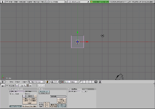
What you’re looking at is the main 3D window with “toolbars” at the bottom. You’re viewing a cube right in the middle of the grid from above, using the top view; the red and green arrows are the axis while the black dot to the right is a light. The tetrahedron-looking shape at the bottom right is the camera position, direction and frustrum in can you want to switch from top, side, etc. views to camera view. For now ignore everything except the cube.
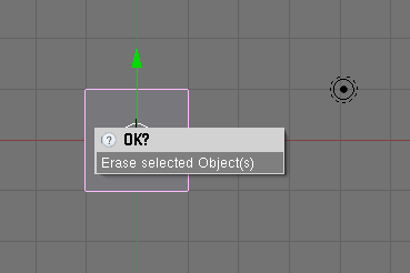
Blender has the nasty habit of inserting a cube on every new Blender file. We won’t need it so we must remove it. It’s selected by default (notice the pink contour) so deleting it is a simple matter of hitting the “Del” hotkey. You’ll get a confirmation dialogue box (see below). Either click where it says “Erase selected Object(s)” or hit “Enter”. The cube should now be gone and the toolbars at the bottom should be hidden.
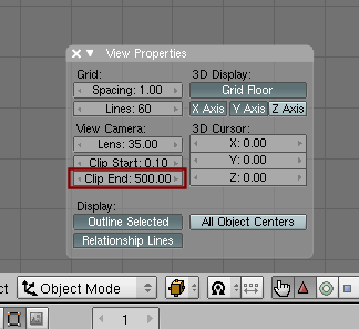
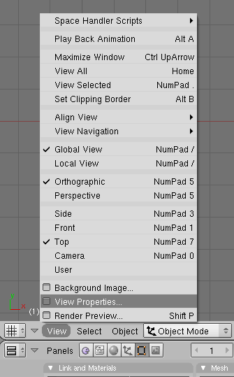
Before we do anything else though, let’s make Blender a little more similar to the level editor. Go into “View > View Properties”; in the small translucent window that appears change both the spacing and divisions values to 8 by clicking directly in them and typing “8”. While you’re at it, change the “Clip Start” and “Clip End” values. Set the former to 1 and the latter to whatever size you want your terrain to be. For instance, if you’re doing a 16384 by 16384 terrain, setting 16384 here will work reasonably well. When you’re done, click the little “x” on the top left on the small window.
Adding a terrain
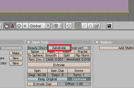
Now click “Add > Mesh > Plane” and you should see a flat pink plane with a yellow outline. Use the mouse wheel to zoom in and out. On the bottom of your screen you should see a button called “Subdivide” as shown in the image below. Click on it until you get enough mesh complexity.
You can keep tabs on how many polys your terrain has by looking at the values on the top right of the screen. The value you’re most concerned about is “Fa” or faces. The first value is how many are currently selected while the value after the hyphen is the total number of faces in your terrain. Every time you hit subdivide the number of faces quadruples. If you think you’ve gone too far you can hit Ctrl + Z to undo. The number of polygons your terrain should have depends entirely on the terrain itself, what it’s used for, etc. Obviously, interactive terrain is going to need more complexity while scenery terrain won’t. The important part to remember is that, like with textures, it’s better to start with detail and then scale back. Pre-emptive optimisation can lead to problems later on.
Now let’s import our terrain. We do this by using the previously created “heightmap.bmp” file as a noise when we deform our plane in Blender. First things first, add a material to the scene. You can do this by clicking the button “New” shown below:
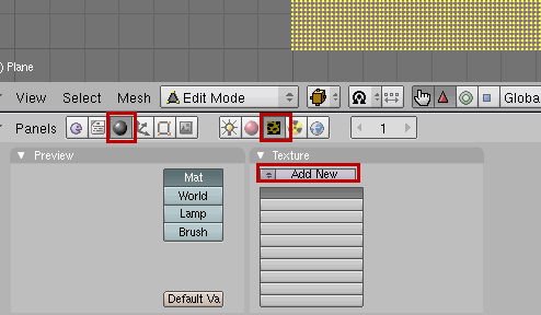
After that, you click the little sphere button entitled “Shading” (or press F5) and then press the yellow and black brick on the centre mini-toolbar entitled “Texture buttons” (or press F6); you then press the “Add New” button to add a new image to the material you’ve created. In the “Texture Type” combo box select “Image”. Two new button areas should appear, press the “Load” button on the right.
You should now be looking at something that closely resembles DOS Shell so it’s okay to feel like you’re back in the late eighties. You’ll need to navigate to the place where you kept your “heightmap.bmp” file. If you’ve been saving your progress on the desktop you need to go to C:\Documents and Settings\<yourwindowsaccount>\Desktop. Once you find it you need to left click on it until the filename appears on top and then right-click on it until the file is highlighted with blue. Then hit the “SELECT IMAGE” button on the right part of the screen. You should now be able to see your heightmap in the preview area below.
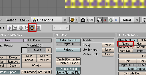
Now we have to return to where we were. Press the button showing a black square with four red vertices entitled “Editing” (or press F9) and then hit the “Noise” button in the centre:
You’ll need to keep hitting the “Noise” button until the height of the terrain reaches roughly what you want proportional to the side. To better see this you can change your perspective from “top” to “side” (or “front”). To do this, select “View > Side”. Don’t worry about getting the height exactly as we’ll be changing this in a bit.
Now it’s a good time to save your file. Go to “File > Save as…” and you’ll be greeted by the same DOS Shell like look. Just find a directory, type the name of your file on the second textbox but leave the “.blend” extension and click the “Save As” button located on the right. You should always save to a different file. Throughout the rest of this tutorial we’ll be making some major changes to the mesh which might be tricky to restore and it’s important that you can go back to a previous version if you make a mistake without having to go through L3DT and EarthSculptor routine for this same terrain.
Scaling the terrain
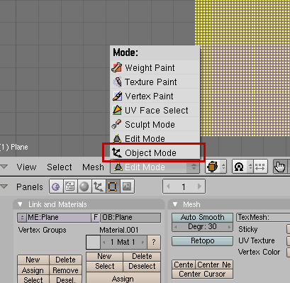
Now that we have deformed our mesh using our heightmap we need to scale the terrain. First go into “Object Mode” as shown in the image below and then select “Object > Transform Properties” from the menu that appears.
A small translucent box should appear. The values we’re concerned here are the “DimX”, “DimY” and “DimZ” values. The first two should read “16” so replace these with the size you want your terrain model to fill in the editor in game units, for instance, if you want a 16384 x 16384 terrain then put “16384” in both “DimX” and “DimY”. You should consider clicking the “Link Scale” button beforehand though. This will let you scale height automatically but only use this if both X and Y dimensions are supposed to be equal.
TIP: In Blender, light coloured buttons are disabled, while a dark coloured button mean that function is enabled.
Smoothing the terrain
After scaling the terrain you may need to zoom out. As you can see in Blender the terrain looks very faceted because you can see every polygon. Click the “Set Smooth” button to fix this.
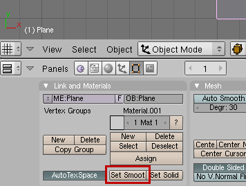
We don’t want this to happen in the game too so we’re going to tell the terrain exporter to manually smooth the polygons over.
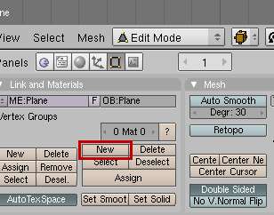
Firstly make sure the terrain is selected (it should since we haven’t yet messed with selection – you can select/deselect everything in Blender by pressing A – toggle it until you get the pink outline) and then select Edit mode from the listbox and look below to the “Link and Materials” toolbar.
When you selected Edit mode a new set of six buttons appeared under “Vertex Groups”. Click the “new” button and a new two new gray fields should appear right above it.
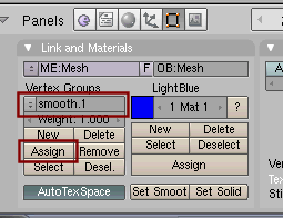
The first is the name of the vertex group you just created. Change the name to “smooth.1” as indicated in the image above and hit the “Assign” button which assigns the current group to all selected vertices (which is all of our terrain in this case). If all went well you should be able to hit the “Select” and “Desel.” buttons right beneath that to toggle the selection of your terrain (faces turn yellow when selected or you just see pink dots when not selected).
You can have more than one smoothing group obviously (you need to pick and choose which faces you want to group instead of grouping the whole terrain into a single group) however, for our purposes where we just want a model of the terrain it’s not needed. If you had a terrain where you wanted some man-made structure built right into the model however, you would group all the vertices that make up the “terrain” into a smoothing group and leave out the vertices that compose the building or whatever. Since any man-made structures will be added in the level editor afterwards instead of right into the terrain model we don’t have to worry about this. Now is a good time to save to another file.
UV Mapping the terrain
NOTE FROM A NOOB reader, it appears that the UV mode was removed and merged with the edit mode around 2007? And you press “u” while in edit mode? If so the following section may need editing….
You’ve probably heard of this expression but put simply, it’s how you wrap a texture around a model. You might also have heard the cries of anguish over a particular model’s UV mapping nightmare; this comes about because a texture is (usually) a 2D format while a model is representation of a 3D volume. You most likely already encountered this problem if you ever used patches and curves on your maps. It’s hard to get the textures to line up correctly on patches, especially if you want them to tile onto brushes, etc.
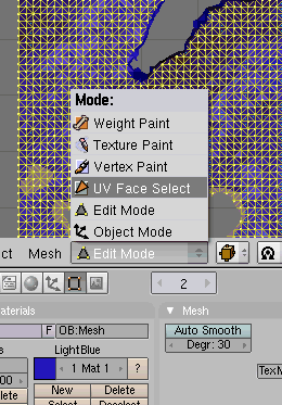
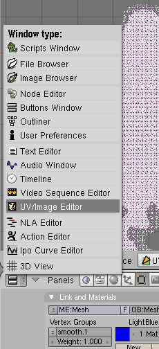
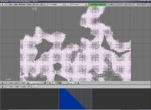
For our purposes here, UV mapping is very easy. We are simply going to “lay the texture down on the terrain” as if it were a sheet on a person laying in bed. We do this by selecting “UV Face select” mode as portrayed in the image below and you’ll note the terrain mesh turns pink. Next, we select the “UV/Image Editor” from the lowest window type button.
You should now have something that resembles this:
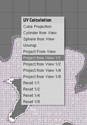
Move the mouse pointer to the 3D view area and press “U” and a floating menu called “UV Calculation” should appear. Select the “Project from View 1/1” option (or “Project from View (bounds)” depending on your version of Blender). You can now revert the lower half of the screen back to “toolbar” mode by selecting “Buttons Window”. Save again to another file.
Exporting to ASE
Before we can use the terrain in the level editor we must export it into a model format the engine understands. Click “File > Export > ASCII Scene (.ase) v0.6.10” (or whatever version of the exporter you’re using). In Blender’s file explorer find the last .blend file you saved and click the “Export ASCII Scene” button on the top right. A small dialogue box should appear.
Make sure you disable the “Selection Only” button and enable the “VertGr. as SmoothGr.” button. Wait until Blender finishes and you should have an . ASE file in the same directory you had your .BLEND file.
Getting it to the game
Make a copy of the .ASE file and put it in the /base/models directory and open it with a text editor . It’s not relevant here to know the structure of an .ASE file but the important thing is that the format lists one or more materials and then one or more 3D objects, each of which point to one material defined in the file. We only have one object, our terrain, and we also should only have one material (unless something went wrong along the way). Look at the file in Notepad and see that you have something similar to this:
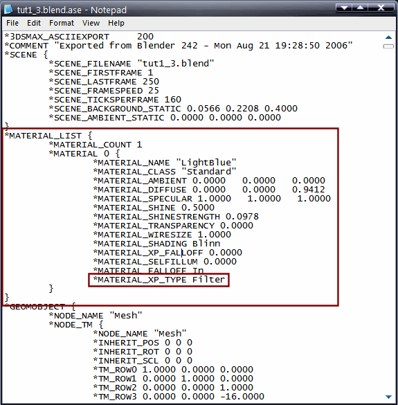
Right near the start you should have a block of text named “MATERIAL 0”, go to the last line highlighted in the image above, “*MATERIAL_XP_TYPE Filter” and paste the following text after that line:
*MAP_DIFFUSE {
    *MAP_NAME "Map #6"
    *MAP_CLASS "Bitmap"
    *MAP_SUBNO 1
    *MAP_AMOUNT 1.0000
    *BITMAP "\\q4base\textures\myterrainmat.tga"
    *MAP_TYPE Screen
    *UVW_U_OFFSET 0.0000
    *UVW_V_OFFSET 0.0000
    *UVW_U_TILING 1.0000
    *UVW_V_TILING 1.0000
    *UVW_ANGLE 0.0000
    *UVW_BLUR 1.0000
    *UVW_BLUR_OFFSET 0.0000
    *UVW_NOUSE_AMT 1.0000
    *UVW_NOISE_SIZE 1.0000
    *UVW_NOISE_LEVEL 1
    *UVW_NOISE_PHASE 0.0000
    *BITMAP_FILTER Pyramidal
}
Save the file; it should now look like this:
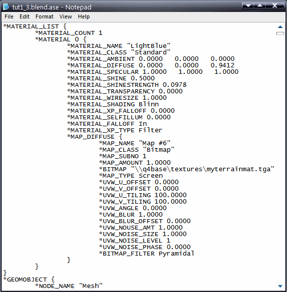
You can set the *BITMAP “\\q4base\textures\myterrainmat.tga” line to anything you want just make sure you include \\base\ (or \\q4base\ if you’re editing for Quake 4) and that it points to a valid material name, not texture (the .TGA extension is not needed). For this tutorial we’re going to create this material called myterrainmat . Before we do that, let’s put all the textures into place.
 Note: Enemy
Territory: Quake Wars only:
Note: Enemy
Territory: Quake Wars only:- Instead of editing the *BITMAP line, ETQW expects the material name in the line *MATERIAL_NAME. For example: *MATERIAL_NAME “textures/myterrainmat”.
As you may know, there is a naming convention when editing textures for id Tech 4 engine. The diffusemap should have the “_d” suffix, the normalmap should have the “_local” suffix, etc. Take the previously exported “texturemap.bmp”, convert it to .TGA (24-bit uncompressed) and save it as “myterrainmat_d.tga” into the “/textures/” folder. Do the same for the “normalmap.bmp” and save it as “myterrainmat_local.tga”. Now let’s create the material declaration :
textures/myterrainmat
{
    qer_editorimage textures/myterrainmat_d

    nonsolid    // Only for scenery terrain
    noshadows   // Can be used in both interactive and scenery
    noselfshadow    // Only for scenery terrain
The nonsolid keyword is appropriate for 3D Skybox terrains but you should obviously leave it out for interactive terrains; you can leave the noshadows keyword for either terrain type because our diffusemap already has the lightmap backed into it and the stencil shadows generally look wrong unless the polygon mesh is very dense. You’ll want to leave out the noSelfShadow keyword for interactive terrains otherwise shadows cast by surfaces which also have that keyword (the player model for instance) will not be cast onto the terrain.
 bumpmap textures/myterrainmat_local
    diffusemap  textures/myterrainmat_d

    {
        blend   filter
        map textures/roughdirt_d
    }

    {
        blend   add
        map textures/myterrainmat_d
    }
}
While a 1024 x 1024 texture resolution is fine for 3D Skybox maps even 2048 x 2048 is not enough for interactive terrains unless they are very small. To improve the overall quality we’re going to fake a detail texture layer. We do this by filtering in a very rough looking texture that has no distinctive features because we want it to tile and tiling a texture with prominent characteristics can give away the tiling effect quite easily. For this tutorial the terrain will be using this texture:
Missing image: /w/images/f/ff/Terrain_24.jpg
All id Tech 4 engine games released so far have plenty of similar looking textures so find one that fits your own terrain textures. Below you can see a comparison screenshot of the same terrain with and without the detail layer.
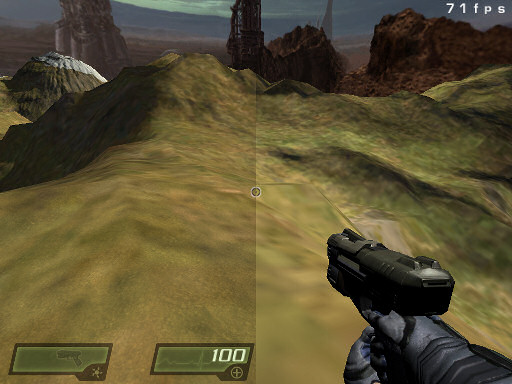
Finally, we add back the texture we used for the diffuse map to restore the original hue removed by the filter stage .
- Note: Enemy
Territory: Quake Wars only:
-
If you intend to use a MegaTexture with your terrain you should reference the following material instead:
material megatextures/myterrainmat {
   useTemplate megatextures/default_ambient< "myterrainmat" >
}
Wrapping it up
You should now have a fully functioning terrain in your map however there may still be some work to be done. You may want to reduce the mesh’s complexity and/or the texture resolution (for memory budget or file download reasons) or perhaps you need to have holes in the terrain to build caves, etc. for your interactive terrain. All of this is should wait until your map nears the optimisation phase and you’ve firmly decided your terrain placement, lighting conditions, etc.